
For some time I’ve toyed with the idea of building my own cnc router, or perhaps a 3d printer. The idea, of having a tool which allows me to fabricate parts using a computer to control the process, is pretty compelling.
More and more there seems to be good information available from others taking on similar projects. Rapid replicators ,thing-o-matics. Plus a range of websites and instructibles on making everything from desktop cnc engravers ,all the way to bed sized cnc routers capable of carving patterns into whole doors.
Off-the-shelf cnc machines are expensive beasts, and not really within reach of the average DIY workshop. But in truth, even if they were cheaper, half the attraction is to make one myself.
So this weekend just gone, I started work on what I imagine will be a long term project.
I decided to start with the 3-axis rig, rather than the motors/electronics. Mostly because I figured I could make this part for less initial outlay than the electronics side.
I spent a lot of time looking at websites that sell cnc parts, showing that you can buy all the components, precision ground rails, linear bearings, pillow blocks etc etc. But decided that even that level of construction seemed too expensive (and too easy)
I may yet discover that I blow more money on trying and failing to use other materials. And I’ve certainly found frustration with achieving good enough results on my chosen linear slide setup.But more of that later.
The first thing I ordered was 30 bearings. I found an ebay listing that got me 3 packs of 10 skateboard bearings for about £11 including p&p which seemed a pretty good deal. Considering they normally come in packs of 8 for ~£5
I knew I’d need the bearings, but I hadn’t really decided on a design at that point. This probably speaks volumes to the ratio of enthusiasm to actual ability 🙂
I decided it would be easier to work with box section than any kind of tubing, and cheaper than precision ground rails. Even at B&Q I got 3 meters for about £22. From what I had seen the precision ground rails are between £2-£3 per 100mm so would have been that much for 1m. So far so good.
Why 3m? Well i figured I wanted no waste, and I could use a 700mm x-axis ,500mm y-axis and 30mm z-axis. (note this won’t be the size of actual workable area due to the frame and the sliding carridges.) This ratio seemed reasonable and left me with no waste.
The plan for the carriage is to cut a plate of metal, and mount a pair of right-angle brackets at each end. The brackets will be angled out to 90Degrees of each other. This should let me bolt the bearings in place. For this idea I basically needed 24 of everything.
Being impatient to start I got everything at B&Q which was probably a mistake as it cost way too much to get this many.But still I got some suitable looking right angle brackets and a bunch of nuts&bolts, M8’s to fit the bearings and M5s to fit the brackets. The plan was to drill out one of the bracket holes to make it an M8.
So having got my first wave of parts I was left with this pile of parts:

And a running total cost of ~£70. Honestly I should have got the bolts from screwfix, even with delivery I could have spent half on the hardware, and I am going to be buying replacements from there anyway. I’ll explain why later.
First I cut the box section into the lengths I wanted, and laid out the pieces on the floor.

I’d read in various places that it’s best to start with the z-axis then the Y-axis to mount it to, ending with the x-axis. I think this way you can ensure as you go that each section is able to bear the weight of what will mount on it. It would be annoying to complete everything up to the z-axis then realise it’s far too heavy for the x-axis carriage to hold upright.
So my plan for the z and y carriages is the same. 2 metal plates, one for either side. Holes trilled at each end of the plate will take the brackets bolted to hold pairs of bearings at right angles. The box section will be mounted with corners facing in ,and the plates will run between. I drew a bunch of sketches in my notebook whilst trying to figure out the best options:

For the metal plate I decided to use the top from an old tv table. I’ve kept hold of this for something like 4 years after disposing of the rest of the table. I figured a big sheet of 5mm metal (steel?) Would come in handy for something. I was even able to use a couple of pieces that already had holes in. My hacksaw was able to cut it fairly easily and soon enough I had two small plates for the z-axis carriage.

Although they had one hole already ,I needed a matching one at the other end, and a central larger hole for the threaded rod to pass through. And so to my trusty pillar drill. Without this tool, the project would be impossible. Certainly to use metal parts.
I’ve had my pillar drill for several years, and until now have used it exclusively for wood. I knew I’d need to adjust it to a slower speed for metal ,so I popped open the top to find it has two belts between 3 sets of pulleys. There are about 10 combinations yielding differing speeds. I decided to put it on the slowest option and go from there if necessary.
I also knew was that I’d need some lubrication to stop everything over heating. Given how much sawdust is in my garage I was keen to avoid very hot metal. Fortunately I looked up advice and found a helpful forum post reminding me that WD40 is flammable! And as such would be a very poor choice of lubricant in this case. Instead I needed some light oil. I realised I had a pot that came with a plane sharpening system (one of those with double-sided stone for coarse/fine grinding and a wheeled runner to mount the blade in) this oil worked a treat, as did the slow speed. Before I knew it I had some nice precise holes in my plates.

I just took it slow, always drilling a small pilot hole, before stepping up to the size I wanted. I kept putting oil in place, and everything worked very nicely. You can see in the picture that I bolted the two plates together through the first hole, to make sure everything stayed lined up. This produces a perfectly aligned pair.
The central hole was drilled up to a 9.5mm hole. This was then tapped to take an M10 threaded rod. The tapping worked nicely and I went through both plates in one pass. In theory I now have a perfect alignment to have the carriage run up and down on threaded rod gripped by both sides of the carriage. In practice of course it was not that easy…
Drilling one hole of the brackets up to M8 was easy (don’t forget the oil) and after quite a bit of cutting and drilling I was ready to assemble the first pieces.
The idea on these small plates was to bolt 3 brackets at each end. 2 to hold bearings and 1 to face front as a mount point for a block of mdf ,which in turn would ultimately mount the rotary tool/router (I have the former, the later I’ll buy if things look like the work well)
This turned out to be pretty tricky

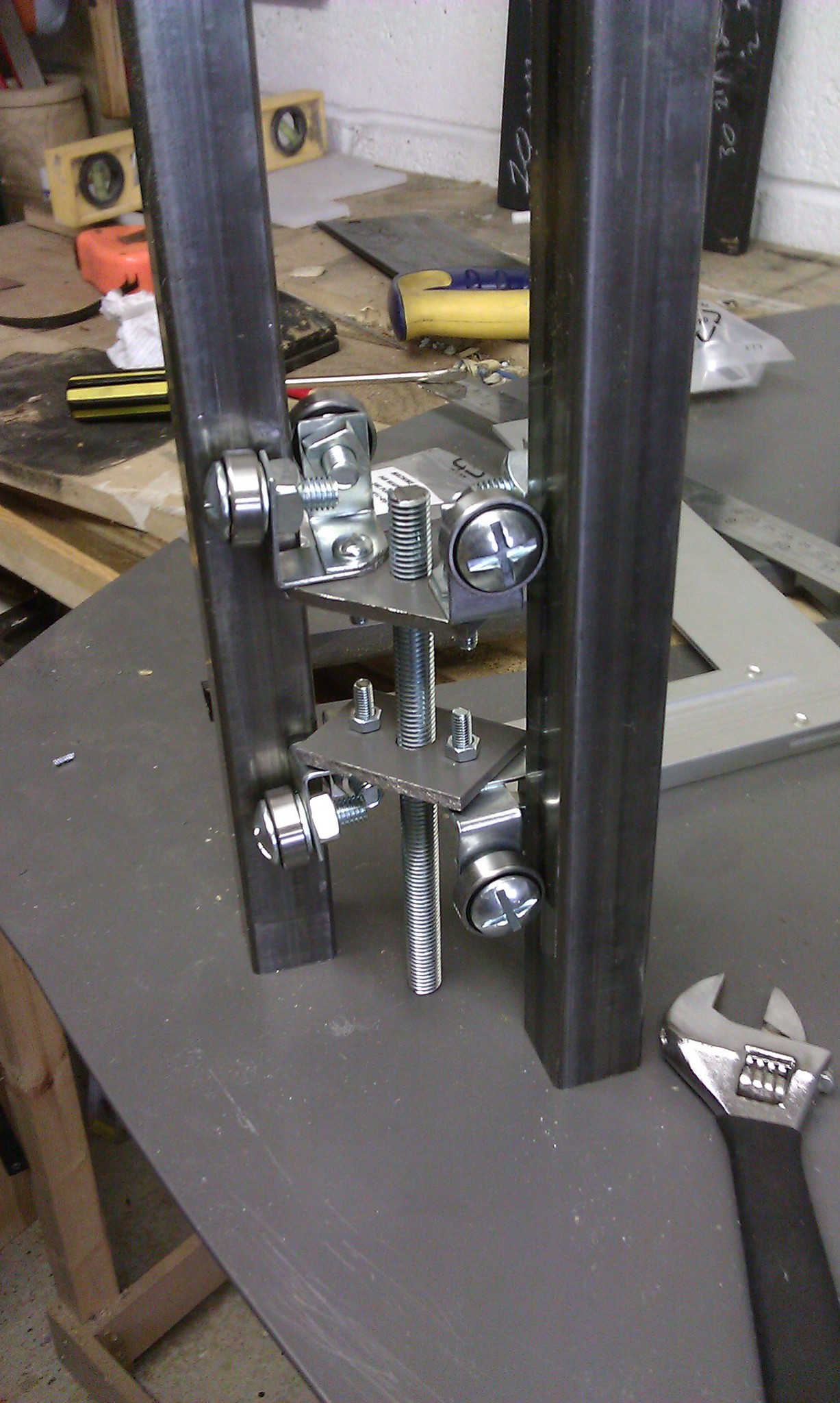
Firstly, as you turn the nut, the whole bolt wants to turn. And in doing so move the brackets out of alignment. Secondly the bolts I got from b&q had flat screwdriver slotted heads. These are basically impossible to get a good grip on whilst also holding the whole assembly in place. As a consequence currently I find the joints give way under load. More on this later.

Having basically assembled two plates with brackets and bearings, bolted as tight as I could, I then screwed a piece of mdf onto the front facing brackets to provide a mount point for what would ultimately be the tool clamp. It was at this point that slight differences in the brackets meant that the centre holes for the threaded rod are pulled slightly off from each other. Just enough to clamp the rod too hard to turn. I could fiddle with it to try and make it better. But in truth threading through just one plate gives a pretty good connection without backlash ,so I may just widen out one hole and leave it gripping on one side only.
With the carriage as assembled as it was going to get, I turned to mounting the square section to provide the rails to run against.

One of the reasons I went with square section was that it would be easier to cut straight edges out of wood to form Vs for the square section to sit in. Rather than attempt to get a perfect tight fit in a square hole, I drilled holes at each end of square section to take screws. Basically I went all the way through with a 4mm bit, then widened the top hole to fit my drill/driver’s bit holder. So I’d be able to set the metal bar in my V groves, then screw them down to hold position. This worked well and I achieved a pretty solid fixing whilst also getting the two bars nice and parallel. This way is also easy to disassemble should I need to.
So here is z-axis at this point:

What I don’t have yet is a long enough piece of threaded rod to mount in place. And obviously I need to resolve my bolt clamping force to ensure things don’t move with the weight of the router etc.
I decided to move on with the Y-axis plates, rather than go buy more bits. This time the plates would be much longer to accommodate holding the z-axis. I quickly realised that my trusty hacksaw wouldn’t be able to cut the length of metal I wanted for the Y-axis plates. So I turned to my jigsaw. Another tool used exclusively for wood cutting until now. I was very pleased to find I already had some hss metal cutting blades, so I set it up, clamped things in place and set to it. It was fairly slow going, but it did the job well enough, and after some more careful drilling (don’t forget the oil) I had a pair of Y axis plates ready to go.

You see here I again bolted through the first few holes as I made them to be sure nothing slipped out of alignment.
Another 8 brackets adjusted to take the M8 bolts and I soon has the Y-axis carriage fitted out. I took a little more care with the alignment of my front facing brackets, but still once screwed onto a board, the threaded holes were just a fraction too far out of alignment. Definitely going to open up one side and allow the thread to bite on the side closest to the motor.
And that’s as far as I got in the first weekend. Pretty much I stopped at the point I realised (with some frustration) that the m5 bolts with stupid slotted heads were never going to tighten enough to hold the brackets/bearings out at the correct angle under load.
So what’s next?
I’ve realised I need to make a tightening jig, that will hold everything in the alignment I want whilst I tighten the bolts.
I also realise I’ll be much happier if I buy some hex head, or allen head bolts to give me more torque on the tightening. This combined with nylon-insert nuts should let me achieve a much higher clamping force.
So a screwfix order this week ready for the weekend!
4 responses to “Cnc router project. Part 1”
[…] Software engineering and woodwork BlogAboutNavit StuffWitter « Cnc router project. Part 1 […]
Do you have check the accuracy of that cnc router ?Is it also possibel to mill on aluminium or is it only for milling foam etc. ?
Its allredy an interesting DIY construction ! CONGRATULATION for that work.
Frank
sadly I don’t have it operating at all yet. work pressures have meant this had to go on a back burner for a long time. its still on my list to buy the motors etc, however until then this just sits at the corner of the workshop full of unused potential. My aim was to built something that could mill through at least mdf, so when I eventually get around to continuing this project I’ll keep at it until that objective is reached.
Please also have a look at theis website:http://www.cnc-router.com/cnc_router/products-cnc-milling-machines-router/high-z-milling-and-engraving-machines-routers/cnc-router
Its a german fabricator of low cost cnc routers with many experencies. They have sold around 4000 cnc routers since 2005.
Are there some customers from CNC-router.com weho let me know their experencies with the cnc routers from cnc-router.com ?