


If you have been following along at home, then you’ll know that last time I had a successful attempt at engraving a sign. With one main caveat. The backlash on the x-axis was still evident and ran to about 2mm.
During the week I tried rebuilding the x-axis captured nut setup to have 2 captured nuts which is common in ánti-backlash arrangements. I did the same on the y-axis and made an attempt to improve the overall alignment. Sadly this did not fix the backlash issue on the x-axis. I was just about to pack up for the day when I thought to just move the x-axis by hand to see the ‘play’ in it and look for signs as to what is moving. Once again I kind of kicked myself for overcomplicating things in the past and not just realising this was the simplest way to check for the problem in the first place.
This quickly revealed the real issue was the x-axis coupler. If you have really been following the whole series of posts, you may recall that early on I sheared off the first x-axis coupler when I had the alignment slightly off. In my haste to get things up and running again I didn’t really allow any time for the silicone to set, my impatience meant that the coupler didn’t wind up with a nice tough rubbery layer joining the two pieces in a firm connection. It wound up squidging out of place and left the couple with… you guessed it… 2 mm of extension/compression movement. Every time you changed directions it first had to compress or extend the coupler.
So after berating myself for the various failures that both caused the problem and took so long to diagnose it. I was happy that I had a spare coupler which I joined with silicone at the same time as the other. So this was now very much set and I could just switch it in.
It worked! I would now estimate that the backlash in all axis to be somewhat less than 1mm, certainly less than I can currently measure.
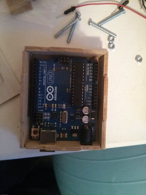
My first run with a fully armed and operational cnc rounter…

I was particularly pleased with this both due to the end result and due to having started from nothing on the same day. I designed the box in openSCAD over breakfast in the morning, Generated the tool path in PyCam over coffee. And finally spent an afternoon running the sequence and creating the real physical box. To be fair the design was just a copy of one I found on thingiverse and originally I was going to use that. However I needed to make adjustments to the part layout to fit the wood I wanted to use. I also had intended to use 5mm hardboard but the thingiverse design was for 3mm. After making adjustments in inkscape, I then had trouble getting pycam to successfully generate a toolpath and I didn’t really understand why. So I created my own parametric model in openSCAD. Same design, but with the ability to change a variable like material thickness and have the whole thing automatically adjust. (openSCAD is awesome) . I uploaded my derivative design here. I love that thingiverse has built into it the idea of expressing the lineage of a design, you can set links to show where inspiration came from or what parts you used.


Whilst I’m at it, I think its time to acknowledge that my own CNC creation was possible due to ‘standing on the shoulders of giants’. Lets list out those giants…
To control the motors you need motor driver boards, sure I could have tried to design my own, but I went for sparkfun easy drivers designed by Brian Schmalz

To send logic signals to these I needed something to interface with the computer. I came across GRBL which is an awesome open source gcode interpreter that runs on an arduino. The Arduino Uno itself is a cool piece of kit and pretty cheap, with lots of help and resources around it.
Then of course there is PyCam another amazing free program for generating the gcode from your models. it has some quirks, and can be very slow at 2.5D models, but for 2d stuff is generally very fast. And its FREE!
At the top of the chain, as I mentioned before is openSCAD Which lets me model what I want in a very ‘programmer’ sort of way which I find easy to work with.
Atop these giants building my CNC router was possible, and relatively cheap. Having done some research, gcode generators (CAD) programs alone can cost $250+ which is a steep ask for a personal project. So I am immensely grateful for the work of these other projects that made my own possible.
2 responses to “DIY CNC Router – Making my first thing! an Arduino Uno box”
[…] by [Daniel], CNC Routed Wood […]
[…] vous invite à vous rendre sur le site du créateur pour télécharger les gabarits et le tutoriel afin de réaliser ce superbe boitier en bois pour […]