

Last week I wrote about the one hour challenge I set myself to setup my raspberry pi with its new camera module and get it running as an IP camera along with my other 2 dedicated ones. This led naturally on to wanting it to be set up a little better than precariously balanced on boxes and blue-tac’d in place. So I set off on another one our project to see how far I could get in building a case. Whilst 1 hour was no where near enough to do everything I wanted, it was a good way to prompt me to action. The challenge of an hour forced me to stop procrastinating and make some decisions to get going. Once the hour was up I was well on my way with a vision of what I wanted to do and so the weekend challenge was on 😉
In the first hour

The first hour was really a case of making the big decisions. I started with 15 minutes sketching out ideas and thinking through things like inserting a nut in the bottom so that I could potentially mount the whole thing on some kind of bracket via a bolt etc.
Here are my initial sketches
I decided to go with a low flat design that would be stable laying on a surface. I wasn’t worried about exposing any of the ports etc, just power in the back and the camera at the front.
The next decision was material, I considered metal or plastic, but really mdf is what I have laying around the most, and is also the thing I have the most tools/experience in working with, so that is what I went with.

The first thing I worked on was how to mount the camera module in a small mdf panel with the camera exposed. Here my new table saw set up made things pretty easy, using the sled I could just cut about half depth slices, and just move the block on each pass until I had a rebate wide enough for the camera module to just fit snugly in place.
I then used the drill press to drill out a hole for the camera lens to poke through.
With this part made I’d essentially determined the height and width of the case I was building, so I could use the bandsaw to cut out a bottom/top and rear to match. I decided to make the long sides from hardboard recessed into slots.
Here I made an unfortunate error, I was just sizing things by eye, but I didn’t yet have the wifi dongle for the raspberry pi, and I didn’t allow quite enough space in the case dimensions, so right at the end I had to hack a little rebate on the inside of the case to accomodate it. I should have done more research about how far it would protrude to get my measurements right up front… Alternately, if I had decided to expose the SD card slot I would have had more room to play with.

My hour was up around about now, I had pieces cut about to size and I knew I could mount the camera module.
What was left to build

As I mentioned above, I decided the long sides would be hardboard set into slots that run alon the bottom/top and up the front and back pieces. This would then get glued in place. I quickly set a stop up on the table saw sled and used it to get repeated slots on each piece that would be hte same distance from the edge. This would have worked perfectly if I had been a little more careful on the bandsaw… Turns out my pieces were not exactly the same width, and so whilst the slots were the same distance from the outside edge on each piece, this left them at slightly differing distances between the slots. So I had to widen a couple to get everything fitting. A lesson learned, in rushing during the first hour I paid less attention to exact cuts, and that caused me trouble later when I decided to use this method of box construction.

With a bit of finessing I was done for the physical construction which really didn’t take that much more than an hour, certainly less than 2. At this point I had a press-fit case of plain mdf and hardboard. I decided to glue up the whole case except the top. The idea being that the top would always remain a push fit, and the means to get the pi in and out.
So I clamped things up and let the glue set (using lots of new clamps I got for christmas/birthday, hurrah for having plenty of clamps!)
The Paint Job

By now I had a pretty good idea that I wanted to use the project as something to play with my new air brush. Being bare mdf, I put on a first coat of primer by brush. This is possibly the only option I had, however the brush marks later frustrated me a little in the pursuit of a nice finish.
I followed the usual routing, paint, dry, sand lightly, paint again. to try and build up a couple of coats of white to give a base for everything else. I wound up airbrushing white on to try and get things looking smooth which was good practice for airbrushing solid colour blocks.
I then set about coming up with idea for what I wanted to paint on the box.

I decided to go with my blog logo on the top, with a raspberry pi logo on the bottom, a power symbol next to the power in hole on the back, and a stylised eye around the camera on the front. This gave me a good chance to practice cutting out templates etc. My logo was tough since the geek is made up of lots of small boxes, this meant lots of very fine bits of paper that needed to be left and not broken during the cutting process. To minimise the risk of screwing it up I cut each letter separately ( this also meant I only needed to cut one ‘e’) and I cut the ‘maker’ separately but as one piece. Finally cutting out the cog shape separately also. This made for a less risky construction of template. However it proved difficult to get things aligning nicely, and I didn’t leave the paint enough time to dry for each part, so putting the template down again to spray the next part lifted some paint from previously sprayed letters.
The raspberry pi logo was pretty straight forward, I did it as two separate templates since it is a two colour template.
For the eye I wound up just free-handing something based on an example I liked. I took measurements from the front of the case so I could sketch my template out to have the camera lens as the pupil of the eye. This probably worked out the best, I’m really happy with how it came out.
Having selected my templates I was thinking about colours and decided I’d make the box itself black, then use the raspberry pi logo colours on their logo and on mine. Then just leave white for the front and back. This involved practising laying down a black coat, then spraying the template with white first. So that the colour would show up on the white. Practice went well, it is reasonably easy to get the template back in place for each pass. However on my paper example the paint dried quicker than it did on my actual case…

practice run
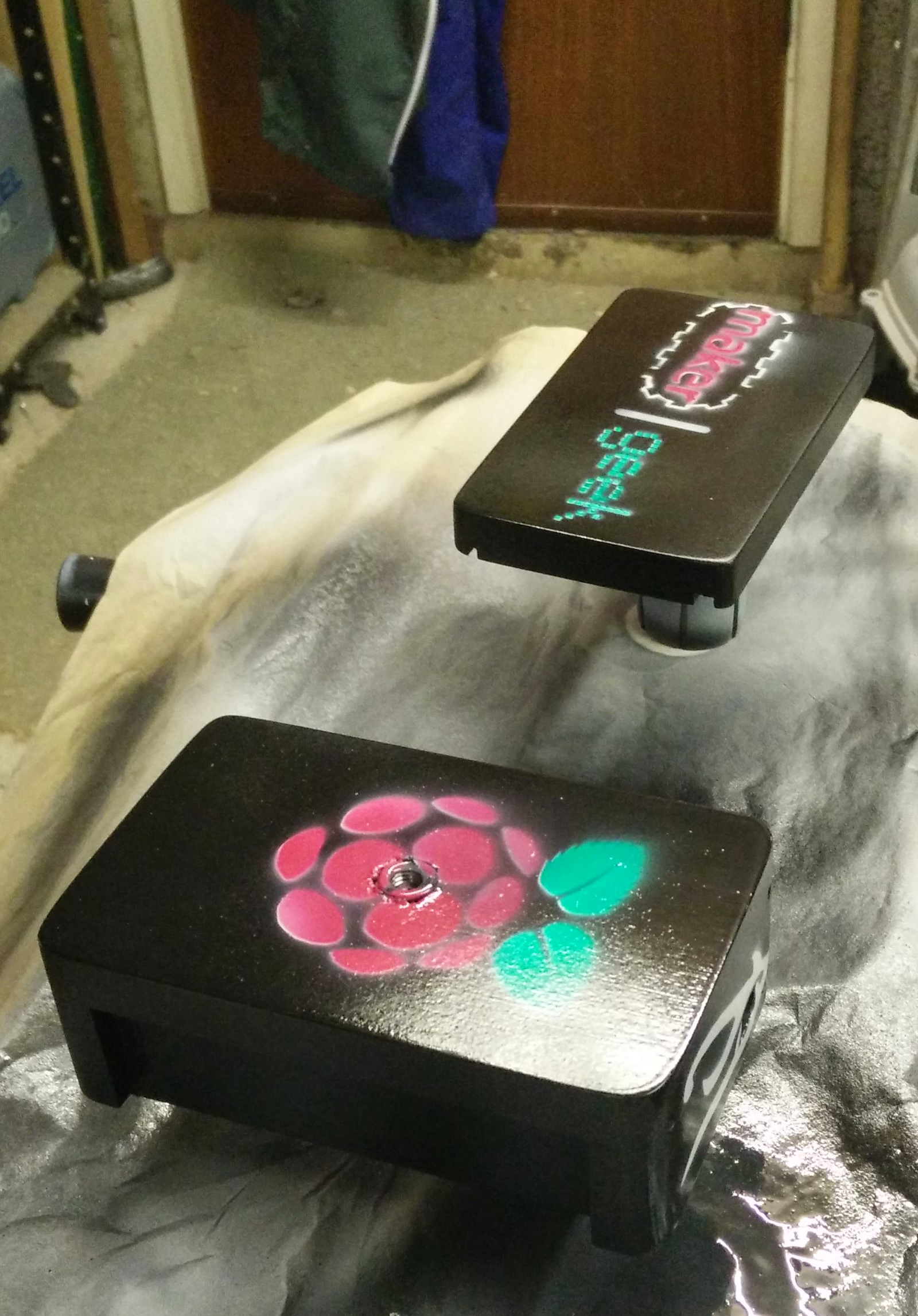
With confidence this was going to work I set about spraying the box black and building up a nice coat all round. I used the nut I had included in the design to allow me to mount the case in the air and let me spray all the surfaces etc.

Around about here is where I was close enough to complete to want to drive to finish within the weekend. Really I should have allowed more time for each stage to dry before moving on to the next. But I was full of enthusiasm and things were looking pretty good.
Here is the box in about its best state, with everything painted, and a clear coat sprayed on to seal everything in place. As I mentioned earlier the maker geek logo was a little wonky due to my decision to template in parts. I’d also made a bit of a mess of the ‘maker’ paint when laying the template down for the geek letters. The green was a little more watery than the other colours so it ran a little more. However despite it all I was fairly happy at this stage.

Unfortunately this is where impatience and earlier mistakes caused problems, I wanted to get the raspberry pi installed, so I didn’t really give the box enough time to dry. It was almost completely dry, but of course my finger found the one corner on the bottom where the clear coat was still wet, and so I got a finger print in it. Perhaps I should have cut my losses here and left it alone to properly dry, but instead I forged on, and discovered the box needed adjustments to let the pi fit with the wifi module installed.
This involved slightly rougher handling of the box, which further damaged the paint on the bottom ;-( It’s not awful, but had I just decided to let the paint all dry over night, I would have found the fit issues with more time available and been able to avoid causing problems to the paint work.

For better or worse, here it is completed within one weekend. From inception to completion was probably 5/6 hours work not including gluing and drying time.


It is cool to have another camera in place and the case is a huge improvement on just propping the bare board somewhere. However I may have to come back to this and make a v2 case to avoid some of the failings in this one.
Did you like this project? Hit like to let me know!
Do you want to try a project like this and need to buy the supplies?